Products Description
| Company Information | |||
| sales@xmjzjsgs.com | |||
| Mobile | +8613666033393 | ||
| +8613666033393 | |||
| 13666033393 |
Parameter
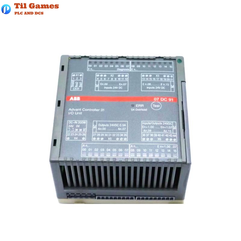
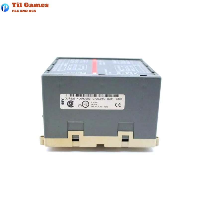
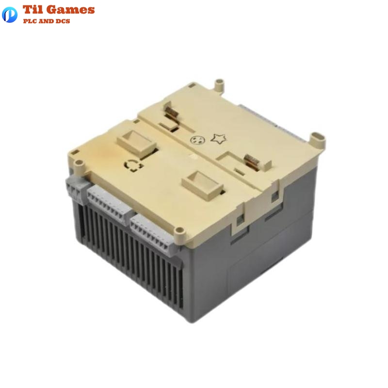
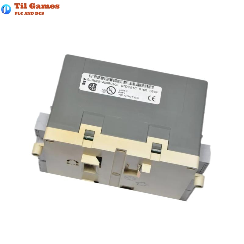
Manufacturer:ABB
Product Number:07DC91 GJR5251400R0202
Product Type:Digital I/O Module
Origin:Sweden (SE)
Dimensions:120 × 140 × 85 mm
Weight:1.07 kg
FAQ
Frequently Asked Questions (FAQ)
Q1: What is the maximum number of I/O channels available on the 07DC91 module?
A1: The module provides a total of 32 channels—16 digital inputs, 8 digital outputs, and 8 configurable channels that can function as either inputs or outputs.
Q2: How is the address for the module set?
A2: Addressing is done using the DIL coding switch located under the slide cover on the right side of the housing. The address is read only during initialization.
Q3: Are the outputs protected against short circuits and overloads?
A3: Yes, each output is protected against short circuits and overloads. When the current exceeds 0.7 A, protection is triggered and the output attempts automatic reactivation.
Q4: What type of diagnostic features are available on this module?
A4: The module supports detection of output short-circuits, overloads, internal errors, and CS31 system bus failures. These errors are indicated via LEDs and transmitted to the central controller.
Q5: How are the configurable channels used?
A5: The 8 configurable channels can be set by the user program as inputs, outputs, or re-readable outputs. Their behavior depends on how they are accessed in the user logic.
Q6: What is the method for visualizing channel status?
A6: Each input channel is indicated by a green LED, while each output or configurable channel uses a yellow LED. A red LED indicates module error conditions.
Q7: What is the recommended installation position?
A7: The module should be installed vertically, with connectors facing up and down. Ensure proper ventilation to allow natural convection cooling.
Q8: Can the module be used in high-frequency switching applications?
A8: The maximum switching frequency is 0.5 Hz for inductive loads and up to 11 Hz for lamps (at max 5 W). For higher frequency switching, consider using relay or solid-state interfaces.
Tags
Packing & Delivery
We will use wear-resistant cartons to seal the boxes, and take photos for your confirmation before sealing. We will pack the boxes only after confirmation.
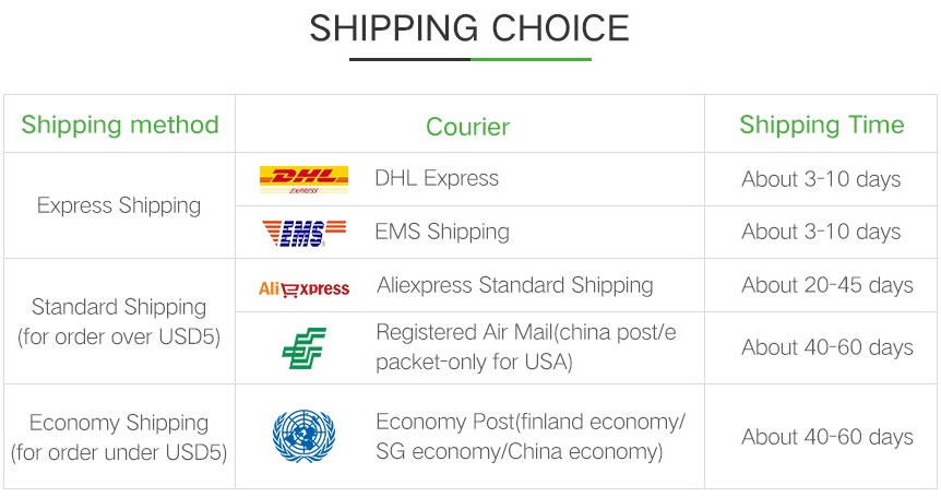
For express delivery, we will use DHL, UPS, TNT, FedEx and EMS.
Please rest assured that we have a deep cooperation with express delivery companies and can ensure that your goods are delivered to you in good condition.